![]()
![]()
![]()
Use LEFT and RIGHT arrow keys to navigate between flashcards;
Use UP and DOWN arrow keys to flip the card;
H to show hint;
A reads text to speech;
249 Cards in this Set
- Front
- Back
|
Requirements for mobility concepts |
vehicle range fast refueling high energy density low price / acceptable safety of engergy storage acceptable efficiency |
|
|
Legal conditions |
Local requirements for single vehicles Coutry-specific requirements for single vehicle Country-specific requirements for vehicle fleets |
|
|
country-specific vehicle fleet regulations |
Europe, China: - vehicle weight = utility value - higher weight --> higher target value USA, Canada: - vehicle contact area = utility value --> Afootpint = wheelbase * track width - greater footprint --> greater target value |
|
|
Relevant components |
Torque Generator Clutches and Transmission Systems Auxiliary Compnents Vehicle Structure Systems Operation |
|
|
Supercredits |
vehicles with CO2 emissions < 50 g/km are counted more, limited to 7,5 g/km in three years |
|
|
CO2 emissions of electric vehicles |
in emission regulations electric veh. have CO2 emission of 0 g/km in serious evaluation also energy production has to be considered |
|
|
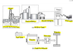
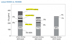
Well-to-Wheel analysis |
|
|
|
powertrain concepts |
standard drivetrain / rear-wheel drive (RWD) front-wheel drive (FWD) four-wheel drive (4WD) |
|
|
Hybrid drivetrains |
Plug-in electric vehicle Hybrid electric Vehicle Electric vehicle with range extender |
|
|
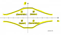
electric motor - torque and power diagram |

|
|
|
four-quadrant operation of an electric motor |
|
|
|
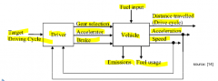
driver as feedback controller |
|
|
|
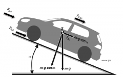
Driving resistances |
|
|
|
tire deformations - moving |
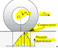
|
|
|
tire deformation - standing |
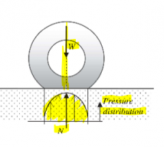
|
|
|
Influencing factors on rolling resistance |
tire construction: type, material, design, diameter tire operating conditions: pressure, speed, temp., load, age, slip road surface: texture, rigidity dryness |
|
|
magic formula (friction coefficient and slip) |
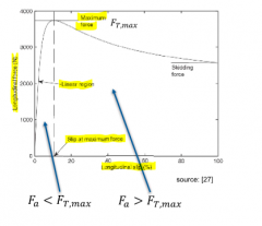
|
|
|
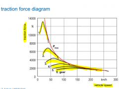
traction force diagram |
|
|
|
dimensioning of gears (gear ratios) |
- lowest gear: drive-off torque for drive-off acceleration and gradeablitity - dimesnioning for top speed (one before last gear) - highest gear: improvement of fuel consumption |
|
|
over-revving vs. under revving |
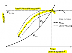
- more acc. with over-revving, but top speed not reached - under-revving minimizes consumption and noise |
|
|
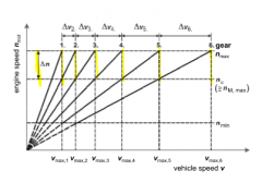
progressive gear stepping |
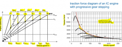
- engine speed increases progressively
- vehicle speed intervals stay the same used in passenger cars |
|
|
geometric gear stepping |
- engine speed changes stay the same - vehicle speed intervals increase commercial vehicles |
|
|
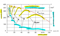
excess power and acceleration capability |
|
|
|
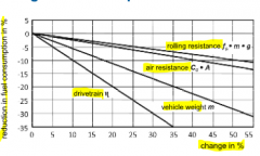
potentials for reducing fuel consumption |
|
|
|
roller test bench concepts |
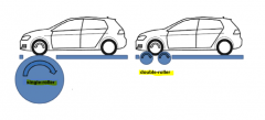
single: closer to reality, but more space needed double: less space, but two contact points |
|
|
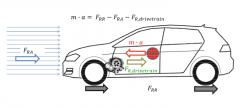
acting forces during coast down |
|
|
|
New European Driving Cycle (NEDC) |
- started with cold engine - additional consumers switched off - MT-vehicles have predefined shifting-specifications, or are operated accoridng gear shift indicator - determination of CO2-emmisons combined and fuel consumption (urban/highway/combined) |
|
|
Worldwide Harmonized Light Vehicles Test Procedure (WLTP) |
- more realistic - harmonized for all global markets - WLTC als test cycle - still roler test benches - 3 different versionas according power to weight ratio -- Class 1 < 22 kW/t -- Class 2 > 22 kW/t -- Class 3 > 34 kW/t |
|
|
changes for WLTP |
- optional equipment considered in vehicle weight, air resistance and energy consumption - batter SOC at 80% - realistic payload - disassambly of components for weight reduction no more allowed - no manipulation of chassis for for air resistance |
|
|
RDE (real driving emissions) in WLTP |
- real road test - minimize manipulation possiblities (software) - PEMS (Portable Emission Measurement Systems) - 90-120 min - no specification of acceleration/speed |
|
|
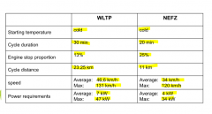
comparison WLTP and NEDC |
|
|
|
NEDC for PHEV-vehicles |
- electrical range of 25 km results in halved fuel consumption - elect. range dertermined by driving until IC-engine kicks in - NEDC is done in electrical mode - recharged energy measure in kWh/100km - CO2-emissions caused by elect. production not considered |
|
|
NEDC for BEW (all electric vehicles) |
- determination of values for energy consumption and range - additional consumers switched off - fully charged, driving two NEDC-cycles - recharging batter afterwards on main supply - measuring energy by power meter - combined value stated - range tested by consecutive cycles until min. SoC (but hardly reachable by customer) |
|
|
combustion engine definition |
- heat engine - chemical energy to mechanical energy - combustion and oxidation with air - rise of temperature and pressure - expansion against mechanical system |
|
|
advantages of combustion engines |
- high energy density of liquid fuels - good efficency (up to 50%) to mechanical work - high performance range - flexible design |
|
|
Problems of combustion engines |
- exhaust gases: smog, acid rain, carcinogenic effects - noise emissions - fossil fuels --> finiteness of crude oil as raw material |
|
|
Classification according: Engine process |
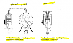
- closed: working fluid not changed, continous combustion outside working chamber - open: air-fuel mixture has to be renewed, hight temp. for short periods |
|
|
Classifcaton according: Operating mode |
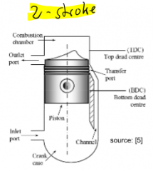
4-stroke: two strokes for gas exchange, two strokes for work generation (intake and exhaust valves) 2-stroke: gas-exchange between working cycles, higher power density, reduced efficiency |
|
|
Classification according: Mixture generation |
external vs. internal (air-fuel mix generated outside cylinder vs. inside of cylinder) (homogeneous vs. inhomogeneous) location of mixture (manifold injection, direct inj., indirect inj.) |
|
|
Classifcation according: Power control |
quality control: mixing ratio of air and fuel is adjusted, mass of working fluid stays appx. constant --> DIESEL quantity control: Intake-mixture-mass is adjusted, mixing ratio stays constant --> GASOLINE |
|
|
Classification according: Ignition |
spark ignition: local energy input from outside (spark plug) --> gasoline engine self-ignition / compression-ignition: high temp. gereated by compression --> diesel engine |
|
|
Classification according: Intake pressure level |
naturally aspirated engines: intake pressure equal or lower than ambient pressure charged engines: additional systems to increase charge density (compressor, exhaust gas driven turbocharger, elect. turbocharger) |
|
|
Classification according: Cooling |
direct or air cooling: ambient air, maximize contact area (cooling fins) indirect or water/liquid cooling: heat transfered to cooling liquid, liquid transfers heat to ambient air by radiator --> reduced max. thermal loads and reduced noise |
|
|
Classification according: Construction |
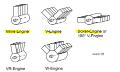
engine alignment |
|
|
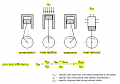
process efficiency IC engine |
|
|
|
Carnot cycle |
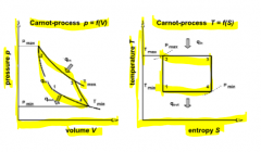
ideal thermodynamic cycle --> max. possible effic. (>70%) for given temp. difference, work per cycle rel. low Isentropic compression (1-->2) Isothermal expansion (2-->3) Isentropic expansion (3-->4) Isothermal compression (4-->1) |
|
|
Constant volume / Otto - Cycle |
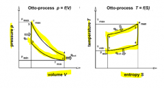
isothermal compression + expansion - heat addition + removal processed at const. Vol. - eff. depending on compr. ratio and thermodyn. propertios of fluid --> max. possible compression ratio, combustion close to TDC position |
|
|
Constant pressure cycle |
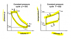
thermodyn. process with limited pressure (max. component load) Isentropic compression (1-->2) Isobaric heat addition (2-->3) Isentropic expansion (3-->4) Isochoric heat removal (4-->1) higher compression increases eff. poorer eff. than Otto |
|
|
Dual cycle / Seiliger - Process |
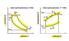
combi of const. vol. and const. press., given compr. ratio and max. press. isentropic compress. (1-->2) isochoric heat addition (2-->3) isobaric heat addition (3-->3*) Isentropic expansion (3*-->4) Isochoric heat removal (4-->1) |
|
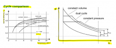
Cycle comparison |
|
|
|
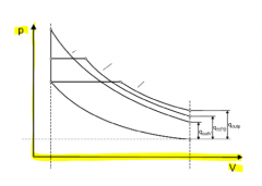
Losses of ideal engines (example Otto-process) |
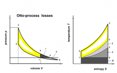
40 % of fuel-energy lost area 1 = expansion not continued to initial pressure area 2 = expansion not continued to initial temp. area 3 = irreversible process |
|
|
efficiency ideal vs. real engines |
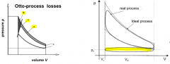
real engines --> additional losses - cylinder wall heat losses (a) - combustion not in infinite short time (b) - throttling losses (c)- heating of intake air - gas exchange incl. flow losses - leakage |
|
|
Engine grade quality |
relationship between real and ideal cycle |
|
|
connection rod to cylinder |
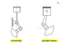
crosshead--> tall engines plunger piston --> passenger cars |
|
|
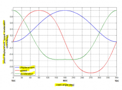
displacement, speed, acceleration of piston |
|
|
|
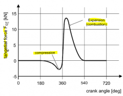
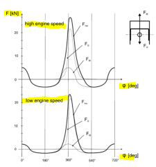
tangential forces depending on crank angle |
|
|
|
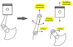
movement types on crank drive |
|
|
|
Forces acting on piston |
Fm --> mass force Fres --> resistive forces Fg --> gravitational forces |
|
|
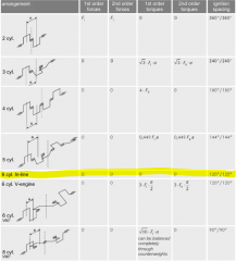
Turning force behaviour of multi-cylinder engines |
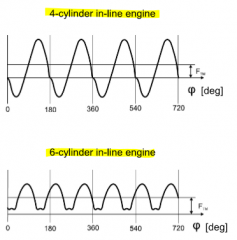
improved engine running smoothness with increasing number of cylinders |
|
|
mass balancing |
- rotary mass forces compensated by counterweights at opposing side - oscillating first order mass forces partly compensated by additional counterweight mass at the crankshaft - 50%-balancing of 1st order forces - no 2nd order forces balanced |
|
|
complete mass balancing (1st and 2nd order) |
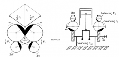
two pairs of contrary rotating balancing shafts |
|
|
balancing multi cylinder engines |
- single cylinders compensate each other - single cylinder parameter, - number of cyl., - arrangment, - crankshaft design - firing order/ignition sequence influence forces |
|
|
mass balancing of multi cylinder engines |
|
|
|
engine characteristic and parameters |
- bore-stroke-ratio s/b = 1 quadratic s/b < 1 short-stroke s/b > 1 lonk-stroke --> Trucks - power - torque - mean-effective pressure |
|
|
Advantages & Disadvantages of long-stroke design |
adv.: advantageaous torque, compact combustion chamber, less wall losses, reduced risk of combustion knock, reduced oscillating masses, reduced crank drive loads disadv.: negative gas exchange at high engine speeds, higher mean piston speeds and accelerations, higher normal force on piston |
|
|
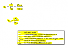
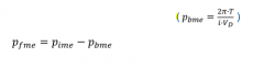
engine power and mean effective pressure |
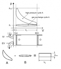
- in-cylinder pressure of a 4-stroke engine - enclosed area corresponds to work done - indicated mean effective pressure pime = Wp/Vd |
|
|
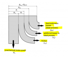
power and pressure of engine |
- available power at engine output smaller than indicated power - engine friction reduces power (piston, valve-train, crankshaft) - driving power for auxiliary components (oil pump, cooling water pump) |
|
|
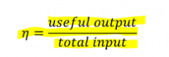
general definition of efficiency |
|
|
|
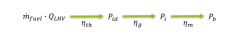
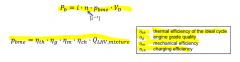
Efficiency chain from liquid fuel to output power |
|
|
|
Sankey-diagram |
|
|
|
determination methods of mechanical efficiency |
frictional power or frictional mean effective pressure has to be measured fired operation: - pressure indication - Willians-line motored operation: - motored measurement - coast-down measurement - cylinder cut-off method |
|
|
indication method |
- most precise method - indication pressure in cylinder is measured (for precision in each cylinder) - break mean effective pressure calculated by brake torque and engine speed |
|
|
Willians-line method |
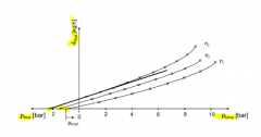
- engine test-bench fuel consumption and break mean effictive pressure are measured for constant speed - graphical solution |
|
|
coast-down measurement |
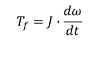
- engine speed decrease after engine shut-down - presice knowledge of mass moment of inertia ist needed |
|
|
cylinder cut-off method |
- used with big engines 1. break power with all cylinders 2. cut-off of one or more cylinders 3. comparison |
|
|
specific fuel consumption |
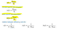
sfc = fuel consumption related to engine power |
|
|
cylinder charge |
- engine power proportional to burned fuel mass during combustion |
|
|
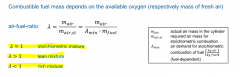
volumetric efficiency |

relation of total aspirated air mass and theoretically possible air mass |
|
|
charging efficiency |
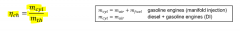
- relation of total mass in the cylinder after gas exchange and theoretically possible mass |
|
|
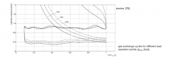
influences of valve overlap on charging efficiency |
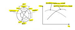
large overlapping --> good scavenging of residual gases at high engine speeds, but return flow of gases at lower engine speeds small overlapping --> good charging efficiency at low speeds, but at high speeds low eff. (worse scavenging) --> vary closing time of intake valve |
|
|
piston speed |
- derivation with respect to time from piston displacement - for high power out, high engine speeds are needed borders: - increasing inertial forces - reduced cylinder charge (flow losses) - raising fricitonal losses and wear - higher noise - dynamic behaviour of valvetrain |
|
|
compression ratio of gasoline engine |
- higher comp. ratio increases engine efficiency - limited by combustion knock - DI engines ratio can be increas. by cooling effect of fuel evaporation - turbocharging increases risk of knocking |
|
|
compression ratio of diesel engine |
- increase potential on efficiency reduced in compression ratio range - high compr. ratio required for cold start ability - reduced compression ratio with charged diesel engines |
|
|
additional characteristic parameters of internal combustion engines |
- power-to-swept volume-ratio - weight-to-power-ratio - specific piston load |
|
|
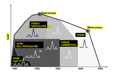
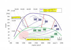
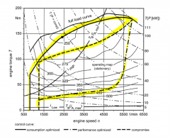
engine full-load curves |
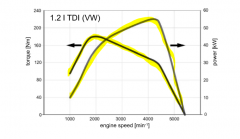
variation of engine operation points defined by speed and torque |
|
|
fuel consumption map |
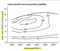
measured data: - speed - torque - fuel mass flow |
|
|
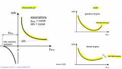
fuel consumption behaviour at constant speed |
|
|
|
bmep vs. engine speed of gasoline/diesel |
|
|
|
mixture generation (gasoline) for complete and fast combustion |
- realize fine vaporisation of fuel - provide correct air/fuel-ratio for operation point (speed, load) -- low and medium loads: λ>1 for optimal fuel cons. λ=1 if 3-way-catalyst used -- full load: λ<1 for max. power - correct amount of gas-mix in cylinder |
|
|
external mixture generation (manifold injection) in gasoline engines |
single injection valve --> SPI (single point inj.) one inj. valve per cyl. --> MPI (multi point inj.) adv. compared to carburetor-system: - higher power - better exhaust-gas quality - better warumup and transient behaviour working principle: - measuring of the air mass flow - dosing the needed fuel mass |
|
|
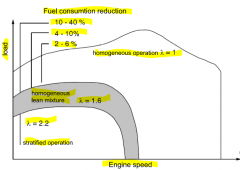
internal mixture generation (direct injection) in gasoline engines |
- fuel reduction in part load operation through lean mix operation (stratified operation) --> unthrottled operation --> reduction of throttling losses - fuel reduction by mix cooling (evaporation enthalpy) --> higher compression ration possible --> better efficency |
|
|
sratified charge concept (gasoline engines) |
- mix with λ~1 surrounds spark plug - average λ can be >> 1 - late injection during engine compression phase |
|
|
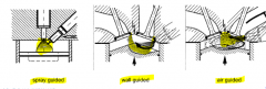
spray guided mixture generation (gasoline) |
- no wall wetting if possible - highest potential for fuel reduction - mix generation quality mainly influenced by spray generation caused by injection valve - problematic: short distance between injector and spark plug (thermal load on injector) |
|
|
wall guided mixture generation (gasoline) |
- spatial separation of injection and combustion - guidance of fuel stream to sparkplug by piston top surface - more time for mixture formation - wall wetting --> increased HC emmisions - non flat piston --> not advantageous for optimal combusiton process |
|
|
air guided mixture generation (gasoline) |
- spatial seperation of injection and combustion - no wall wetting - intensive tumble flow --> complex variable tumble generation system needed |
|
|
advantages/disadvantages of direct injection (gasoline) |
+ gas exchange (fuel consumption through trhottling) + compression ratio (higher through evaporation enthalpy cooling) + real gas behavior influence + reduced wall heat losses (fuel cloud away from walls) - less optimal combustion process - unbrunt fuel/emmisions higer HC-emiisions and soot generation - mechanical losses (higher effort for high injection pressure) --> advantages outweigh disadvantages |
|
|
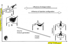
operation modes in mixture generation (gasoline) |
|
|
|
mixture generation (diesel) |
- very short period of time for injection, mix generation, inflammation and combustion - combustion chamber geometry affects mix generation significantly |
|
|
diesel mixture generation combustion chamber types |
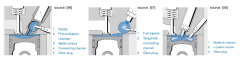
- subdivision in two chambers (InDirect Injection) - Undivided combustion (Direct Injection) |
|
|
Diesel DI combustion chambers |
- development focused on DI-Diesel-engines (better reachable fuel efficiency) - harsher noise can be reduced by modern high pressure inj. systems for multiple inj. (pre-inject.) - creation of effective air turbulence - shape combustion chamber to suport air flow pattern at the end of compression stroke |
|
|
Diesel Injection Systems |
- fuel atomization, heating, vaporization and mixing with air must take place in rapid succesion - two different types of DI inj systems: -- mixture formation assisited by specifically created air-flow effects -- control mixture formation by means of fuel injection and largely dispense with any air-flow effects - |
|
|
EDC (Electronic Diesel Control) |
- high presision adjustment of injection paramters - using electronic injection control - two types of injection system (unit injector, comm rail) |
|
|
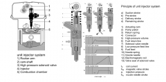
unit injector |
|
|
|
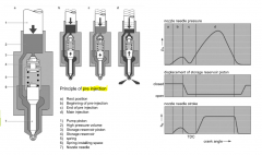
principle of pre injection (diesel) |
|
|
|
common rail injectoion systems (Diesel) |
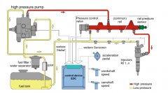
- high pressure fuel reservoir (common rail) - pressure generation done by high pressure pump - injection carried out by (electonically drivven) injectors (solenoid valve- or piezo injectors) |
|
|
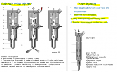
solenoid valve inj. and piezo inj. |
|
|
|
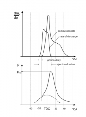
Diesel Injection parameters |
- start of injection (crank angle) - injection duration (specified in degrees or milliseconds) - rate of discharge (fuel mass flow plotted against time) |
|
|
multi injection strategies (Diesel) |
|
|
|
Requirements for good gas exchange |
- large opening crosssections - fast opening and closing of valves - streamlining design - good sealing properties - good durability |
|
|
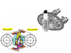
valve timing (1) |
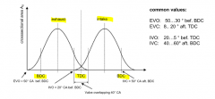
- defines crank angel position where intake and exhaust vavles are opened and closed
- opening times longener than intake or exhaust stroke because of flow areas increase slowly --> valve overlapping in TDC position of the gas exchange cycle (intake and exhaust valve are open an same time) |
|
|
valve timing (2) |
- Exhaust valve timing (EV closes after TDC position) - Intake valve timing (IV closes after BDC position) --> higher charging efficiency due to inertial effects --> at low speeds negative effect on charging efficiency |
|
|
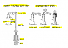
valve actuation systems |
|
|
|
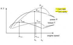
variable valve timing |
- valve timing influences full load power and torque curves of IC engines - camp-phase shifter allow an adjustment of valve timing |
|
|
variable valve lift systems |
- gas exchange losses are crucial disadvatange of gasoline engines - early intake valve closing strategy |
|
|
Electromagnetic valvetrain |
- single actuator for every valve - armature between two solenoid coils --> opening of valve - energization of lower solenoid coil --> closing of valve - energization of upper solenoid coil - disadvantages: costs and package |
|
|
combustion process (gasoline engines) formula |
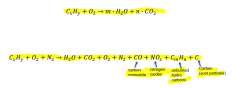
- reaction of a chemical substance with oxagen, releasing heat - requires high temp. levels ideal combustion converts hydro-carbons to water and CO2 |
|
|
combustion process (gasoline engines) diagram |
|
|
|
cyclic fluctuations with gasoline engine combustion |
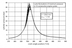
- statisctical fluctuations at consecutive working cycles --> differences in ignition delay and flame propagation --> characteristic fluctuations in pressure curves of consecutives cycles - minimal fluctuations with ari/fuel ration of λ = 0.85 caused by maximal flame speeds in that range |
|
|
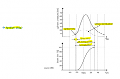
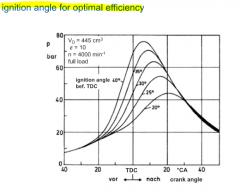
influence of ignition angle |
|
|
|
combustion knock |
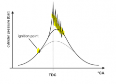
- uncotrolled spontaneous ignition of unburned mixture - initiated at combustion chamber hot spots - reflection of shock waves created through combustion knock - result: steep pressure increase (noise), higher maximum pressures, temperature increase at cylinder walls, high thermal and mechanical loads on components |
|
|
The tendency of combusiton knock increases with |
higher compresion ration earlier ignition point higher intake temperature higher temperature of components rising coolant temp. increased load/filling bigger bore diameter longer burning path decreasing gas exchange movement approach to the stoichiometric air/fuel ratio decreasing rotational speed |
|
|
combustion process (diesel engines) |
- ignition delay --> mixture preparation (atomization and evaporation) - mixture preparation continues during combustion - ingnition delay massivley influenced by pressure and temperature - ignition takes place in vaporized mix |
|
|
parameters of combustion process (diesel) |
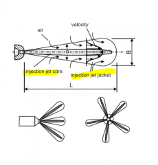
- cone-shaped sprays - droplet size reduces with: -- reduced diameter of injector -- increasing discharge velocity -- increasing air density -- reduced fuel viscosity and surface tension |
|
|
fuel injection (diesel) |
- adjustment of paramters to avoid wall wetting
- fuel injected at end of compression --> fuel vaporizes, mixes with surrounding air, pre-reactions take place --> self ignition when mis parts exceed ignition temp. |
|
|
optimization of combustion process 1 (diesel) |
- objective: good efficiency, low noise, low emmistions - influence of start of injection: --> early start of injection: ---- not yet highly compressed air ---- combustion happens spontaenous with high pressure and temp. --> later start of injection ---- reduced ignition delay and lower max. conversion rate ---- reduced max. pressure + temp. ---- risk of soot formation |
|
|
optimization of combustion process 2 (diesel) |
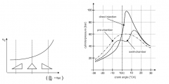
- influence of rate of discharge -- combustion efficiency raises the faster fuel is injected into the cylinder (higher conversion rate) - influence of combustion chamber type -- with divided chamber: combustion starts in prechamber and is transfered in to main chamber -- undivided: steep pressure gradients and high noise |
|
|
emissions of gasoline engines |
limited by law are CO, NOx, CmHn (HC), particles
|
|
|
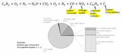
generation of pollutants (gasoline engines) |
- exhaust gas composition primarily influenced by air/fuel-ratio λ - CO-emissions when λ<1 due to incomplete combustion - HC-emissions in zones not captured by flame front --> at air deficiency λ < 1 --> due to misfires λ >> 1 - NOx-emissions --> temp > 1600 K --> with lean (reduced temp) and rich mix (lack oxygen) NOx decreases - |
|
|
stratified DI gasoline engines emissions |
- reduced NOX-emissions: reduced mean temperature level - increased HC-emissions: locally lean areas (combustion stopps) - particle and CO-emissions can occur due to locally rich areas |
|
|
generation of pullutants (diesel engines) |
CO-emissions - very low CO-emissions (high global air/fuel ratios (λ >> 1) - great amounts of CO (λ < 1) --> to CO2 by post oxidation HC-emissions - low with λ >> 1 - occur in locaclly very lean areas - in zones not captured by the combustion - due to unintended wall wetting NOx-emission - occure also with higher air/fuel ratios (compared to gasoline eng.) - in pre/swirl-chamber-engines starts at air deficiency and continues to high excess of air --> low NOx-formation level in both cases - DI-enines have doubled NOx emissions Particulate matter - incomplete combustion - locally very richt mixture areas - carbon atoms - HC-molecules + paricles --> cancer |
|
|
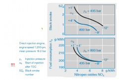
NOx-PM-trade off (diesel) |
- NOx and particulate emissions mutually dependent - crucial parameter = start of injection - early start of inj. (low gas temp) --> ignition delay ↑ --> fast combustion --> steep pressure gradient and high temp. --> less PM, high NOx - late start of inj. (high gas temp) --> ignition delay ↓ --> reduced part of constant volume combustion --> reduced temp --> less NOx, more PM, reduced efficiency |
|
|
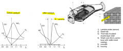
internal measures for emission reduction (gasoline) |
- air/fuel ratio --> presicision of mixture generation and uniform distribution over all cylinders - shape of combustion chamber - stroke/bore ratio - raising the compression ratio minimizes CO and HC emissions, but increase NOx-emissions - EGR (internal or external) reduce temp level and thus NOx |
|
|
external measure for emission reduction (gasoline) |
- three-way-catalytic converters - HC and CO habe to be oxidated and NOx reduced - λ control (λ = 1) - good conversion requieres level of > 300 °C --> warm-up - close to engine installation - secondary air system or electrical heating - warm-up mode realised through retarded ignition angles |
|
|
3-way-catalysts |
- ceramic or metallic monolith - aliminium oxide carrier layer (contact surface maximation) - contains noble metals Pt and Pd (speed up oxidations) and Rh (Rhodium) --> NOx reduction |
|
|
NOx adsorption catalyst |
- air/fuel rations λ > 1 --> no CO for NOx reduction (NOx storage) - limited storage --> regeration necessary - NOx adsoption works at lower temp than 3-way-catalyst - sulfur-free fuels required |
|
|
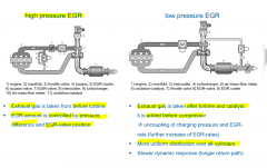
internal measures for emission reduction (diesel) |
- focus on NOx-PM-trade off - mixture generation influenced by injection system - optimized fuel preparation - start of inj. influenced the NOx-and PM-emissions massively - common rail systems provide more freedom for inj. strategy - EGR to minimize NOx (higher rates than in gasoline engines) - combination of high- and low-pressure EGR |
|
|
high vs. low pressure EGR (diesel) |
|
|
|
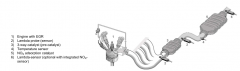
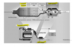
external measures for emission reduction (diesel engines) |
- oxidation catalytic converters -- used for HC and CO oxidation - particulate filters -- remove PM emissions from exhaust gas -- ceramic honeycomb structure (silicium oxid) -- particles deposit at walls -- increasing load --> back pressure --> regeneration at high engine speeds + loads / adapted inj. strategy - SCR (selective catalytic reduction) -- used for NOx reduction -- ammonia to reduce NOx (toxic) so use urea (Harnstoff) (has to be refilled) |
|
|
diesel engine exhaus gas system |
|
|
|
Fundamentals of performance improvement |
remaining possibility for power improvement: CHARGING |
|
|
charging fundamentals |
- increase of charging efficiency by pre-compaction of intake air - raise engine power for more than 100% - but higher loads on valve train and crank train - reasons of charging: -- raise of engine power -- downsizing (constant engine power but reduction of displacement volume) goal: bsfc-reduction |
|
|
advantages and disadvantages of chargin |
adv.: - reduced packaging space - reduced number of cylinder --> reduced length of engine - reduced engine weight (better weight-to-power-ratio) - better engine efficiency (with exhaust gas turbocharging) - reduced power reduction with decreasing ambient air density disadv.: - signifcant higher thermal and mechanical loads - worst torque/acceleration behaviour (turbo lag) |
|
|
torque, engine speed diagram for charged systems |
|
|
|
p-V-diagram of charged engines |
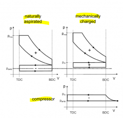
differences of charged diagram: - high pressure cycle shows greater area - clockwise gas-exchange cycle (work generated throug precompressed intake air) - pre-compression is realised by the compressor (counterclockwise cycle --> work required) - work has to be generated by the engine |
|
|
methods of enine charging |
- externally driven charging - mechanical charging - exhaust gas turbocharging - pressure pulsation charging |
|
|
externally driven charging |
- compressor by e-motor - air mass quantity controlled independent from engine speed (good response, flexible torque generation) - today used as assistant charging in combination with exhaust gas turbocharger - disadv.: lower overall engine efficiency (dirving poser for charger) |
|
|
mechanical charging |
- gear-, chain- or toothed belt drive - air mass quantity proportional to engine speed - chargers can be switched off - decreasing torque with reducing engine speed - virtually no efficiency increase at full load operation - good efficiency in part load (compressor can be switched off or bypassed) |
|
|
exhaust gas turbo charging |
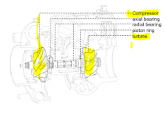
- turbine is driven by remaining energy of the exhaust gases - no mechanical coupling between compressor and crank-shaft - use of exhaust gas energy increases engine efficiency - turbocharger design -- impellers (turbine and compressor) ues radial constructions -- hydrodynamic plain bearings for turbocharger shaft |
|
|
charger operation principles |
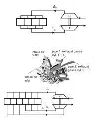
- ram air charging -- exhaust gases flow into an exhaust gas collector/manifold prior to turbine --> nearly constant gas speeds --> good efficiency -- disadv.: increased exhaust gas back pressure --> poor scavenging - pulse charging -- thin pipes --> use of kinetic energy of exhaust gases -- disadv.: permanently changing gas speeds --> pulse losses --> reduced efficiency |
|
|
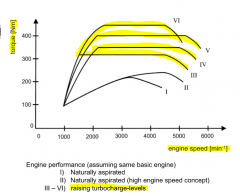
characteristics of turbocharging / design of turbocharger concepts |
- reducing engine speed results in reduced exhaust gas mass flow --> reduced turbine pressure ratio --> reduced compressor pressure ratio --> reduced torque reduction of intake pressure can be compensated by variable turbine geometry or multiple chargers |
|
|
1. Small turbocharger without bypass |
- small turbine generates hight intake pressures at low speeds - good dynamic response because of light weighted impellers - but too high intake pressure at nominal engine speed --> pressure relief valve after compressor (no mor ueses with modern engines because of energetic disadv.) |
|
|
2. Small turbocharger with bypass |
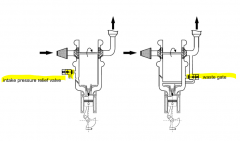
- possibility to bypass parts of exhaust gas flow at turbine to avoid an excess of intake pressure --> waste gate |
|
|
3. Adjustable turbine guide blades |
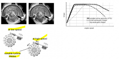
--> variable turbine geometry --> controlable intake pressure at low and high engine speeds |
|
|
4. Use of small parallel turbines |
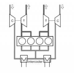
- small parallel turbines for each half of cylinders (bi-turbo / twin-turbo) - combination of good dynamic behaviour of small turbines and high power at nominal engine speed - add. adv. achieved by two turbines operated when needed and only one in part load or low speeds |
|
|
5. sequential use of two chargers |
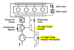
- creation of intake pressure in two steps - small high pressure charger for good dynamic behaviour - big low-pressure charger adv.: good response disadv.: required installation space |
|
|
6. Sequential use of mechanical and turbocharger |
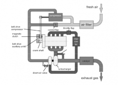
- mechanical charger for good dynamic behaviour - turbor charger --> combination of advantages of both charging systems (VW TSI) |
|
|
cylinder cut off method |
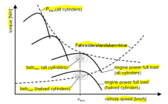
- high potential for fuel reduction (th. 10-20%, real 7%) - injection cut off & valves kept close - disadv.: reduced comfort |
|
|
downsizing diagram |
|
|
|
boundary conditions in IC engine - driven vehicles |
- IC engines operate within specific speed range, limited by idle speed and max. speed - power and torque not offered uniformly - engines rotate in only one direction Requirements for vehicle transmission systems - conversion of torque and rotational speed for traction requirements- slipping operation to allow start of from vehicle state of rest - reversal of rotation direction for reverse driving |
|
|
transmission efficiency
|
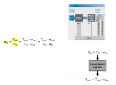
- transmission situated in central position - substantially influence the drivetrain effectiveness |
|
|
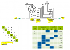
single-disc dry clutch |
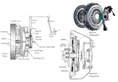
- realize start-up capability, transfering torque using frictional forces - operated by clutch pedal - rotational speed converter - slipping state --> mechanical power from faster to slower disc - Transmittable torque depends on: -- acting normal force -- dimensions of friction lining -- friction coefficient btw. friction partners |
|
|
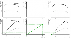
torque and power diagrams at disc clutch |
|
|
|
hydraulic torque converter |
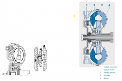
- start-up element used with tourque converter automatic transmission (AT) - works as additional gear - damp vibration system - power transmission via hydraulic fluid |
|
|
operation principle of torque converter |
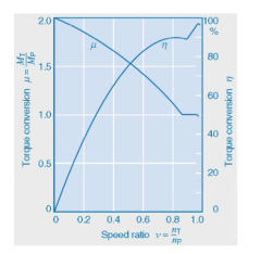
- impeller sets fluid from hub in motion in an outward direction - fluid hits the turbine which directs it inwards - fluid from the turbine in the hub area then hits the stator, which diverts it back to the pump - maximum efficiency < 97 % - transmission of power only takes place when slip occurs |
|
|
transmission parameters |
- transmission should convert torque and speed into a driving tourque at the wheel and rotational wheel speed - paramters: -- gear ratio -- gearing range -- tractive force -- vehicle speed -- gear-ratio steps / gear stepping |
|
|
geometric gear stepping |
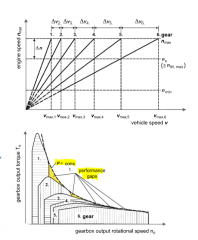
- αgb = const
- change of engine speed Δn constant in all gears - Δv increases with increasing number of gears - uniform distribution of performance gaps - commercial vehicles |
|
|
progressive gear stepping |
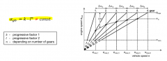
- change of engine speed Δv reduces with raising number of gears - Δv nearly constant with increasing number of gears - performance gaps compared to geometric gear-stepping -- reduced gaps at higher vehicle speeds -- increased gaps at lower vehicle speeds |
|
|
manual transmission |
- simplest and most inexpensive - 6-speed manual transmissions for fuel consumption (standard) - components: -- single-disc dry clutch for start-up -- gears mounted on two shafts -- positive clutches as shifting elements actuated via synchronizer - damping (low pass filtering) required (dual mass flywheel) |
|
|
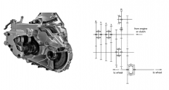
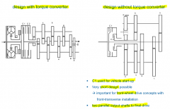
design variants of manual transmission |
coaxial design - rear-wheel drive concept - three shafts: input and output shaft, countershaft - input and output shaft can be connected directly (direct gear) --> countershaft bypassed parallel design - front wheel drive concept - two shafts: input and output shaft (parallel - short installation space |
|
|
Dog clutches |
shift between different gears |
|
|
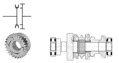
coaxial or in-line design |
|
|
|
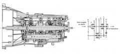
parallel design |
|
|
|
synchronizer mechanism / synchromesh |
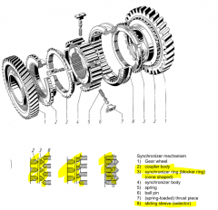
- shifting from one gear to another, input side needs to be accelerated or decelerated - two parts should be locked, spinning at different speeds, teeth will fail to engage - cone clutch engaged before new gear engaged - cone clutch brings the selector and the new gear to the same speed using friction - blocker ring is reliefed and selector and new gear can be engaged smoothly |
|
|
dual mass flywheel |
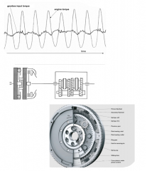
- operating principle of IC engines result in fluctuating crankshaft torques (increasing with reducing number of cyl.) - to provide a nearly continous energy flow, damping system (low-pass) needed - soultion: dual mass flywheel |
|
|
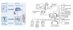
automated manual transmission |
- simplification of the gearbox - lower fuel consumption by optimizing shift points - avoid incorrect shifting to improve long term durability of drive train - gearshift performed by pneumatic, hydraulic, or electrical actuators - transmission efficiency comparable to manual transmission, advantage compared to other automatic gearbox variants - problem: high complexity |
|
|
design and operation concept of automated transmission |
- automated shifting by electronic clutch management, two servomotors for selection and shifting - electronic control signals from shift lever (through ECU) - fully automated systems shifting and clutch actuation are automated (can be bypassed by manual settings) - intervention of engine control for comfortable shifting operation |
|
|
components of automated manual transmission systems |
- basic design as for manual transmissions - actuation of clutch and gear change by actuators - electronic control |
|
|
main features of automated manual transmission |
- compact design - high efficiency - adaptation to existing transmission possible - more competitively priced than automatic or CVT transmission - simple operation - suitable shifting strategies - interrruption of tractive force during gearshifting |
|
|
AST (Automated Shift Transmission) |
- clutch servo unit -- serves to actuate the clutch -- integrated ECU, housing with cooling, DC motr, helical gear, push rod and return spring - DC Motors for Gear Selection and Engagement -- mounted directly on transmission -- selector motor has short response time -- shift motor has high rotational force |
|
|
dual clutch transmission |
- further development of the AST - operate without interruption of tractive force transmission design: -- basic design as for manual transmission -- gears mounted on three shafts -- two clutches to realize mutual gear shifting (sequential) -- two gears engaged at time (active + preselected) --> fast gear shifts |
|
|
designs of dual-clutch transmissions |
features: -- similiar level of convenience to an AT -- high efficiency -- no interruption of tractive force -- skipping of gear possible (interruption of traction force) -- more space than AST -- high bearing forces |
|
|
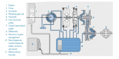
Automatic transmission (AT) desing and components |
- torque converter as start-up elem. -- hydraulic system - gear sets -- planetary gera sets - switching elements - parking lock -- DCT and AT have parkin lock - gearbox ECU -- magnetic/solenoid valves are used to actuate switching elemnts |
|
|
planetary gear sets |
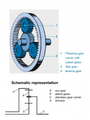
- heart of automatic transmission - central sun gear - several planet gears (rotate around own axis and also around sun gear, held in place by planetary gear carrier) - internal gear/annulus surrounds and encloses the planet gears, internal gear can rotate around the central axis |
|
|
gear ratios of planetary-gears / fixed carrier gear ratio |
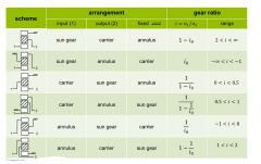
- several ways to convert an input rotation into output rotation -- rotational speeds of the three available shafts -- sever gear ratios can be realised |
|
|
reasons to use planetary gear for automatic transmission |
- power density very high - highly compact and low in weight - no free radial forces occur in the planetary-gear set - multiplate clutches, multiplate brakes, band brakes and one-way clutches can be arranged |
|
|
multi-disc clutches and brakes |
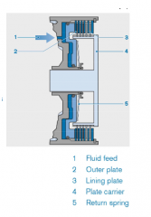
- facilitate shifting without an interruption of tractive force - with clutches both plate-packages (outer and inner are rotating) - with brakes one of the two friction partners is fixed stationary |
|
|
4-speed automatic transmission with Ravigneaux planetary gear set |
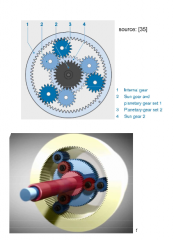
- in the Ravigneaux set two different planetary sets - 4 shafts -- sun gear and planetary gear carrier of the two planetary gear sets can be connected via clutches - kinematic degree of freedom of 2 --> two speeds are spedivied, all other speeds established |
|
|
automatic transmission with ravigneaux planetary gear set |
|
|
|
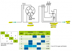
6-speed automatic transmission (ZF 6HP) |
- ravigneaux set can only realize 4 forward gears, - Lepelletier set for 6 forward gears |
|
|
8-speed automatic transmisson (ZF 8HP) |

- 4 single planetary gear set - 5 switching elements |
|
|
Automatic Transmission Fluid (ATF) |
- Power transmission in torque converter - actuation of switching elements - lubrication of gear-sets and wet-running clutches - increased pressure-absorption capability - good viscosity-temp. characteristics - high resisitance to aging - low foaming tendency - compatibility with sealing materials - for lifetime |
|
|
oil pump |
- build up a control pressure for switching elements and operate the torque converter - oil pumps are driven by IC engine - variable pump flow -- pump output adapted as required -- variable pump flow has the drawback of being expensive and susceptible to failure - controlable pump pressure -- pump pressure is adapted to the torque to be transferred |
|
|
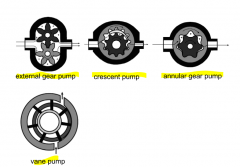
oil pump types |
|
|
|
continuously variable transmission (CVT) |
adv.: - operation of the IC engine in any desired operation point - optimization of fuel consumption - no shifting required disadv.: - limited efficiency because of high power demands for hydraulic system - acoustic vehicle acceleration behaviour |
|
|
design of CVT |
- torque converter or multi-disc clutch for start-up - planetary gearset for reverse gear - gear ratio varied by V-pulleys and putsh belt / link chain (variator) - function controlled by electrohydraulic control system |
|
|
CVT Variator |
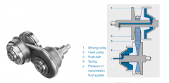
- two V-pulleys moving in relation to each other - alter the position of the push-belt to change gear ratio - power transmission is based solely on the friction --> high system pressure |
|
|
CVT push belt |
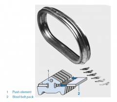
- push-belt consists of push elements - arranged at an inclination angle of 11° - chain held by two packs - coefficient of friction at leas 0.9 |
|
|
CVT Link chain |
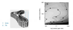
- made completely of steel - transfer very high torques (up to 350 Nm) - very low slip-level --> very low wear --> good durability and efficiency compared to push-belts |
|
|
operation strategy of CVT |
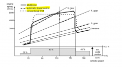
- acceleration behaviour not accepted by costumers --> control strategy adjusted |
|
|
differential gear |
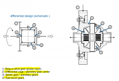
- allows the rotation of driven wheels at different rotational speeds while transferring power from the engine / gearbox to the wheels - additional gear ratio - turn the power flow direction by 90° - input torque transmitted to both wheels 50:50 - drawback: -- one wheel good traction, one wheel slippery track, majority of power goes to slippery wheel --> no tractive force --> limited slip differential |
|
|
boundary conditions for electric mobility |
- stricter CO2 regulations - electrified drivetrains offer a high potnetial to fuel consumption reduction - agreement to sell more elecrified systems - locally emission free driving in urban areas - reduced noise emissions |
|
|
Definition of acronyms (Electrified and Hybrid-Drivetrains) |
Battery electric vehicle BEV - E-Motor as prime mover Range Extended Electric Vehicle REEV - additional IC Engine or fuel cell for mobile recharging Plug-In Hybrid Electric Vehicle PHEV - combination of elcric and IC engine battery chargable at mains supply Hybrid Electric Vehicle HEV - IC engine + Electric motor battery not chargable at mains supply Fuel Cell Hybrid Electric Vehicle FCHEV - electric motor + fuel cell for energy generation |
|
|
Hybrid Drivetrains |
- two prime movers - two energy storage systems - flywheel energy storage systems - hydraulic or pneumatic energy storage systems - potential for fuel reduction |
|
|
advantages of electrified drivtrains |
- energy-efficient - locally emission-free driving possible - electric motors fit nearly ideal to vehicle traction force demands - noise emissions lower - pure electric vehicles show simple design and can be controlled easily |
|
|
disadvantages of electrified drivetrains |
- high inital purchase costs - low range and log chargin durations -- nominal ranges of 150-200 km - need for quick charge stations -- no sufficient infrastructure -- charging times still around 30 min vs. fuel tank 1 min |
|
|
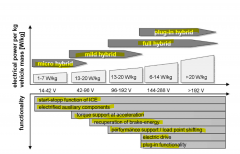
levels of hybridisation |
|
|
|
Micro-hybrid |
- according definition no real hybrid (only one prime mover) - start-stop function - recuperation on relatively low power levels (2-5 kW) - no electical driving possible - no high-voltage electrical system - fuel reduction 5-10% in NEDC-cycle |
|
|
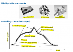
Mild-hybrid |
- e-motors power of 5-25 kW (parallel hybrid concepts) - recuperation of brake energy at higher power levels possible - boost mode for acceleration - load shifting (limiting factor: battery capacity) - no electrical driving or very short range electrical driving capabilites - high voltage (42V-150V) - fuel consumption reduction influenced by E-motor-power and battery capacity - high potential for fleet CO2 reduction at limited costs - fuel reduction potential: 10-20% |
|
|
mild-hybrid components and operating concept |
|
|
|
Full-hybrid |
- installed e-motors power of 15-60 kW - operation modes: -- start-stop operation -- recupteration of brake energy -- boost mode -- load point shifting -- elecrical driving -- high voltag electircal system (150-450 V) -- batter capacity 4-10 Ah -- fuel reduciton potential 20-30% |
|
|
Plug-In-Hybrid |
- similiar to full-hybrid concept - higher e-motor power --> increased speeds - higher battery capacity --> higher ranges (el.) - battery less power more capacity oriented - connector for battery charging on main supply - fuel reduction > 50 % |
|
|
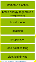
hybrid functions |
- combinding adv. of IC engine with el. eng. - high ranges by ICE, locally emission-free by electrical - intelligent interaction of both systems |
|
|
start-stop function |
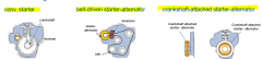
- engine switched off at vehicle rest (AT) or at very low vehicle speeds (MT) - MT: gearbox shifted in neutral position, clutch closed - AT: brake vehicle into standstill - prevent engine shut down if: -- engine or catalyst temp. to low -- turn indicator switched on -- batter SoC to low - starter-alternator replaced normal starting device - fuel reduction potential: 5% |
|
|
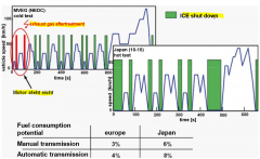
fuel consumption by start-stop system |
|
|
|
brake energy regeneration (using alternator) |
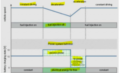
- intelligent alternator management - restricted use because of limited power of the system - in over-run/braking mode, voltage set point is set to higher values (15V) --> more power produced by alternator - acceleration mode, voltage set to lower value (12 V) --> alternator switched off, energy demands covered by battery --> dischargin of battery - fuel reduction potential 3% |
|
|
Boost mode |
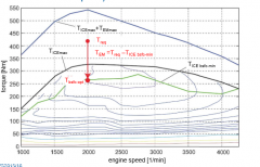
- simultaneous use of both prime movers for acceleration - increased max. torque and power (limited period of time) - no direct fuel reduction potential, but possible engine downsizing |
|
|
Coasting |
- uncoupling of the prime movers from drivetrain - shifting to neutral gearbox position - rollin of vehicle without engine (and e motor) --> drag losses - only efficient if no mechanical braking required during coasting phase |
|
|
Recuperation |
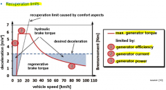
- convert kinetic vehicle energy into electrical energy using e-machine in generator mode - limiting factors: -- acutal available e-machine power -- chargin current/power of battery -- battery SoC -- comfort and convenience aspects -- safety aspects - complex brake systems - only acting on one axle |
|
|
recuperation strategies |
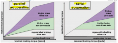
- parallel recuperation: -- frictional and regenerativ braking simultaneously -- distribution with fixed proportions on both systems -- reduced recuperation potential - serial recuperatoin: -- first step: only regenerative braking -- second step: frictional braking if first is ot sufficient -- more complex |
|
|
Load point shifting |
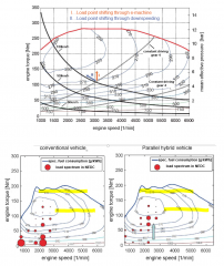
- ICE show high fuel consumptoin at low loads - good eff. at low or medium speed and high loads - shifting of ICE operation to higner engine load - EM in generator mode --> excess of power into battery - or downspeeding reducing engine speed at constant power demands |
|
|
electric drive |
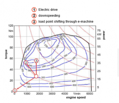
- propulstion power generated only from e-motor - ICE switched off --> no fuel consumption - constant driving and accelerating capabilities - electric range depends on content of traction batter - auxiliary compenents have to be electrified |
|
|
potentials of hybrid functions |
|
|
|
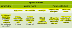
hybrid drivetrain concepts |
|
|
|
serial hybrid drive |
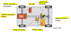
- optimal for high stop-and-go-proportions - adv.: -- load point shifting -- flexible positioning of ICE -- motors can be installed very close to the wheels - disadv.: -- low efficiency (multiple energy conversions) -- three energy converters (ICE, 2 e-motors) -- high effort, cost and weight |
|
|
paralles hybrid drive |
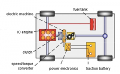
- mechanical connection of ICE and e-motor along drivetrain - normally only one e-machine necessary (two possible) - varying positions of e-machine in drivetrain --> Px-hybrid (P for parallel, x represents position) - adv.: -- easy, cost-effective integration of e-mach. -- easy realization of different, adv. operation modes (start-stopp, recuperation, elec. drive, load point shifting, boost) - disadv.: -- operatoin points of ICE and e-mach. not independent -- difficult packaging in existing drivetrain |
|
|
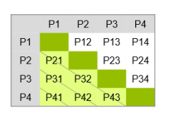
P1 hybrid |
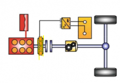
- e-machine is installed rigidly at the back of the engine crank shaft (easy integration in exist. drivetrain) - easy realization of load point shifting and boost - very good start-stop capabilities - recuperation possible but reduced by drag losses of ICE - el. driving not possible, only with rotating engine - fuel reduction lower than with other hybrids - typical mild hybrid |
|
|
P2 hybrid |
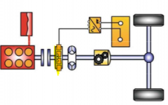
- clutch betweed e-mach. and ICE - variant 1: -- no torque converter between e-machine and gearbox -- e-motor replaces torque converter -- for start stop either additional starter or knowledgre of exact ICE position needed - variant 2: -- torque converter btw. e-m and gearbox -- ICE start done by e-motor without add. starter - all hybrid functions realizable - max fuel consumption possible with this concept |
|
|
P3 hybrid |
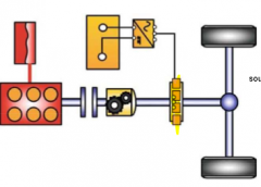
- e-motor at gearbox output before differential gear - enhanced comfort during gearshift - limited load point shifting capabilities - boost mode easy to realize |
|
|
P4 hybrid |
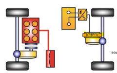
- e-motor on rear axle - for higher recuperation better to install e-motor at front - start-stop additional starter needed - load point shifting difficult (power transfer via road) - boost mode easy to realize - simultaneous operation of ICE and e-motor enables 4WD - no battery charging at vehicle rest possible |
|
|
Combined parallel hybrids |
- at least 2 e-motors - in all combinations of P1x ideal start-stop function can be provided (by e-motor 1) |
|
|
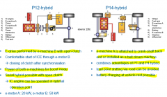
P12 hybrid and P14 hybrid |
|
|
|
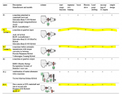
hybrid drivetrain concepts of manufacturers |
|
|
|
power-split hybrids |
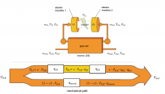
- splitting of mechanical power that should be transferred into a mechanical and an electrical proportion - electronically continous variable transmission (E-CVT) can reduce the complexity of transmission system - coupling of gear sets with electrical variator of two e-machnes (one motor, one generator) - splitting of input power done by planetary gear set |
|
|
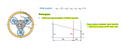
Willis equation / Nomogram |
|
|
|
E-CVT system |
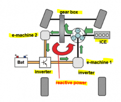
- circulating energy from mechanical to electrical part and back into mechanical path (reactive power) - negative impact on gearbox efficiency |
|
|
E-CVT operation modes 1 |
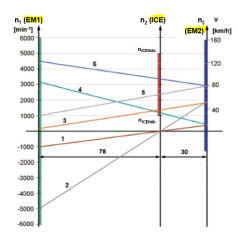
1. Electrical start-up 2. Electric drive (up to 50 km/h) 3. Engine start 4. Vehicle start-up with IC engine 5. Driving at medium speed and lower power demands 6. Driving at same speed but higher power demands (uphill) |
|
|
E-CVT operation modes 2 |
1. Driving at max. speed and max. power 2. Driving at high speed and medium power demands 3. Driving at high speed and low power demands (downhill) |
|
|
Other hybrid drivetrain concepts |
- output-split - compound-split - dual-mode hybrid |
|
|
ICE engine modification for hybrid drivetrains |
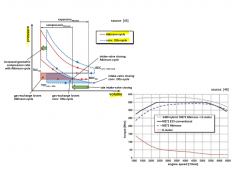
Aktinson cycle - otto cycle particulatrly suitable for hybrid concepts - Intake valve opening time is significantly extended and geometric compression ration is increased - risk of combustion knock avoided by late closing of intake valve - reduction of gas excange losses |
|
|
Electrical machines |
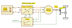
- convert electric energy into mechanical energy - can be operated as generator - power electronics for e-machine control - supplied by direct-current source |
|
|
types of e-machines |
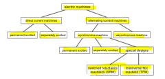
- stationary part (stator) - rotary part (rotor) |
|
|
operating limits of e-machines |
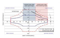
- nominal range (long-term use possible without overloading) - overload range -- short-term use witch significantly higher torque and power -->limited through winding temp., mechanical strength, machine temp - smaller machine to average requirements - power peaks and short time torque deficiency (turbo lag, start up) can be covered by overload operation |
|
|
alternating current machines |
- rotating magnetic fields generated by three-phase power supply - rotary fiel windings ar installed at e-machine stator - 3-phases A.C. current 120° phase shifted supply the three windings --> rotating magnetic field |
|
|
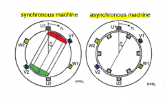
asynchronous machines (induction machines) |
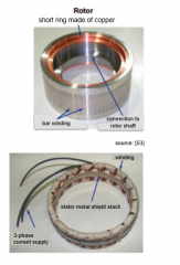
- squirrel cage rotors (stack of metal shields, bar-winding armature) -operating principle: -- induction of current in the winding of the rotor -- torque created |
|
|
seperately excited synchrounous machines |
- DC-current excited field-spiders (rotor field generated through slip ring supply of windings installed on salient pole rotors) - excitation current can be reduced to 0 -- no- load losses also at high rotational speeds - constant flux at field spider disadv.: - additional shaft lenght caused by slip ring system - costs for additional power supply system for excitation adv.: - good efficiency - low weight |
|
|
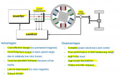
Permanent magnet synchrounous machines (PMSM) |
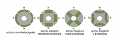
- most commonly usesd e-machine for vehicles - permanent magnets generate excitatoin field --> very good efficency (up to 94 %) - rare earth magnets needed - small instalation space - stator similiar to other AC-motors - design variants: -- external rotor motor --- optimal for high torques and power density --- no problem with centrifugal forces on magnets --- stator coolin problematic -- internal rotor motor --- large cooling areas for stator coolin --> higher power rating |
|
|
Switched reluctance machines (SRM) |
- special design of synchronous motors - based on reluctance torque (rotor moves in direction of minimal magnetic resistance) |
|
|
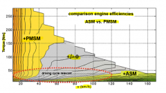
comparison of electric machines |
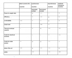
- max. effic. of power elect. are in range of 93-99% - different machine types show their maxima in different operatoin ranges (torque/speed) - max. effic. can be provided with permanent magnet synchrounous machines (but cost intensive) |
|
|
comparison of electric engine efficiencies |
|